A. Visualizing Atomic Structures
1. Initial Setup
- Create an account on Materials Project.
- Download and install VESTA for your operating system.
2. Drill 1: Graphene
2.1 Download the Structure File
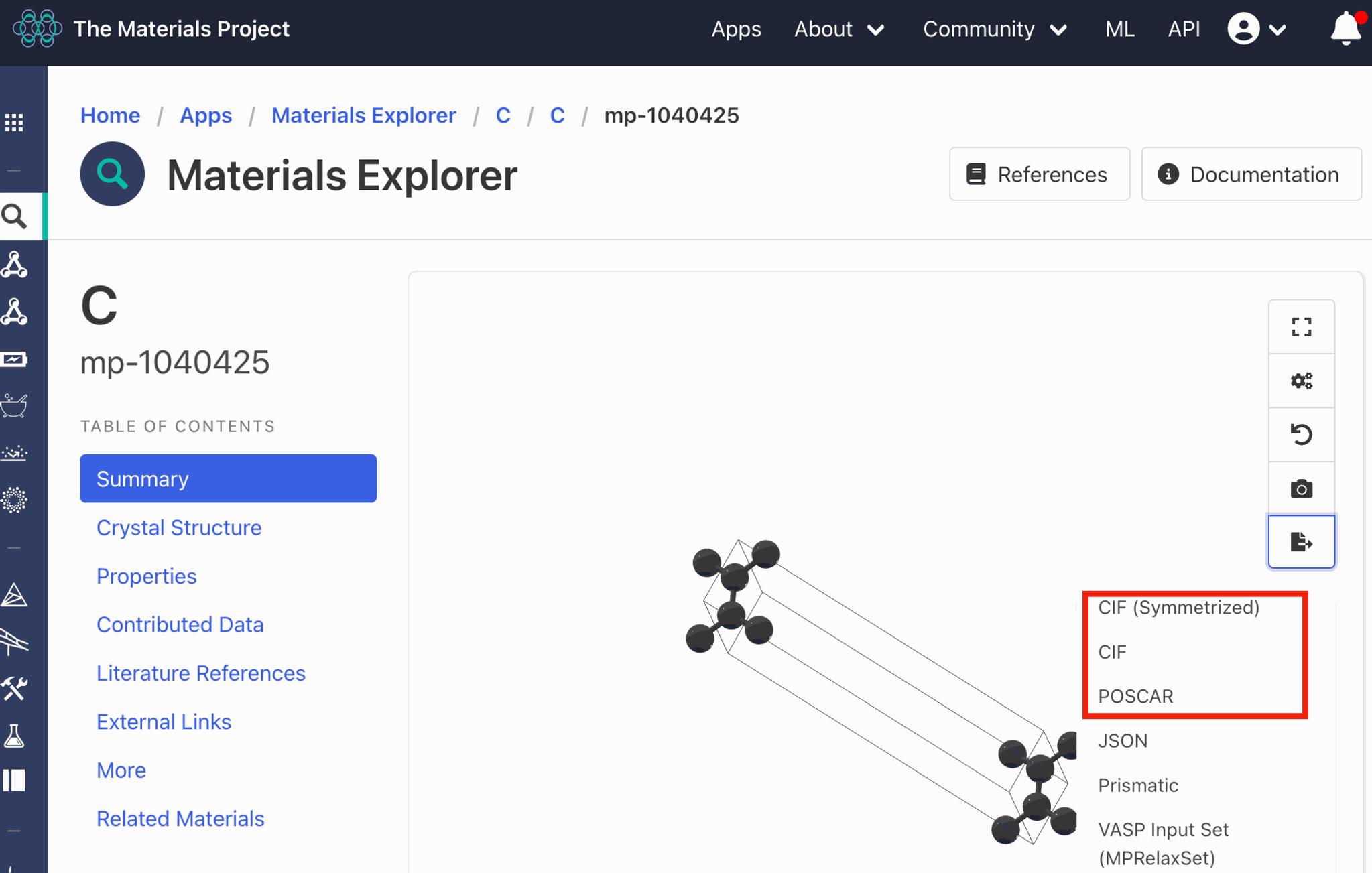
Search for graphene on Materials Project and select the structure you want to visualize.

Download the structure file in POSCAR format.
2.2 Open the Structure in VESTA
Rename the downloaded file as follows:
C.poscar -> C.vasp
Then launch VESTA and drag the C.vasp file onto the empty VESTA window.
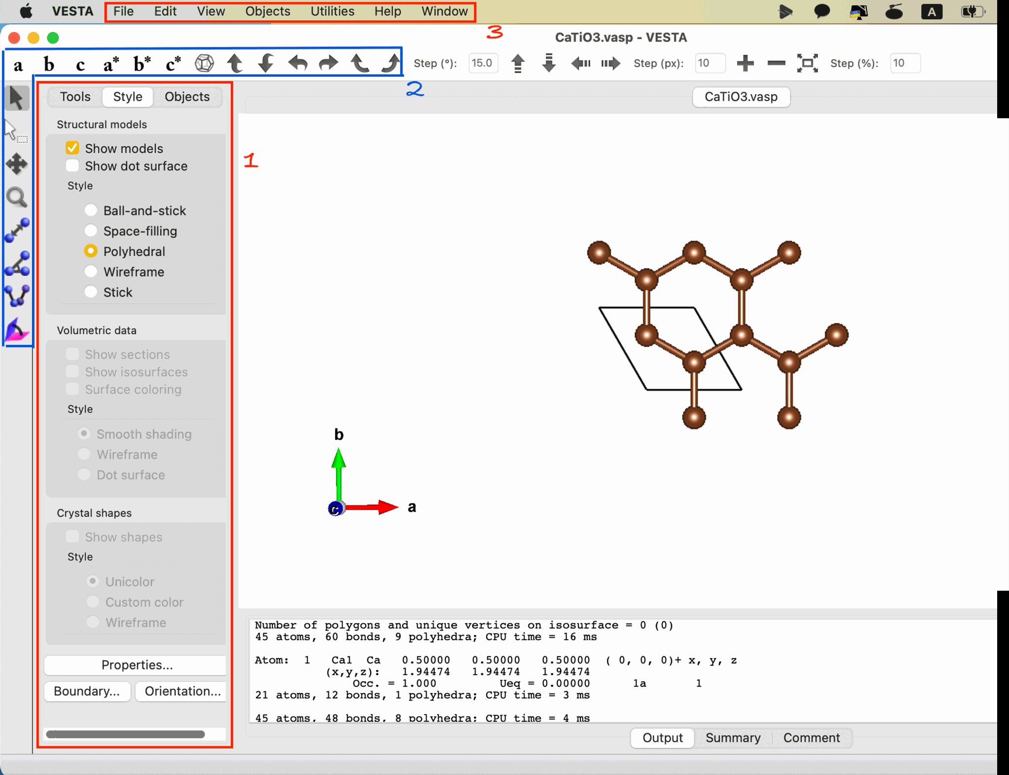
2.3 Adjust the Displayed Unit-Cell Range
Open the following menu located at the bottom left of Box 1:
Style -> Boundary
For example, set:
x(max): 2
y(max): 2
This changes only the range displayed on the screen. It does not modify the actual lattice vectors or create a physical supercell.
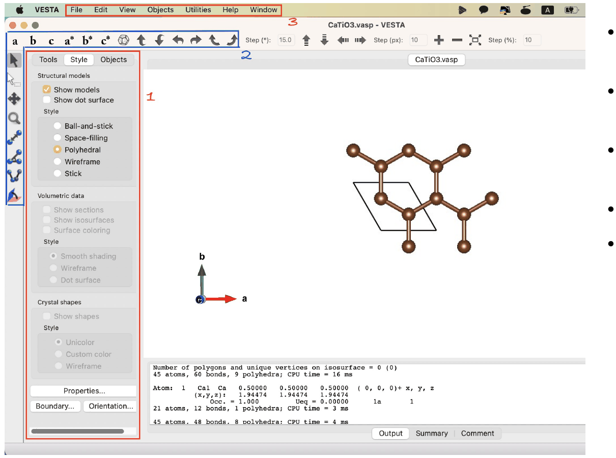
The numbered labels in the figure indicate the VESTA interface areas used in this tutorial.
- Box 1: Style panel: Adjust the displayed range under Boundary…
- Box 2: View/orientation toolbar: Use the lattice-axis and rotation tools to inspect the structure from different directions.
- Box 3: Menu bar: Define or modify bonds under Edit -> Bonds.
2.4 Define C-C Bonds
Open:
[Edit] -> [Bonds] -> [New]
Set:
A1: C
A2: C
Choose a bond-length range that includes the nearest-neighbor C-C distance, then click Apply.
3. Drill 2: CaTiO3
3.1 Download and Open the Structure File
Following the same procedure as above, search for CaTiO3 on Materials Project. Download the POSCAR file and open it in VESTA.
3.2 Use the Polyhedral View
Select the following style:
Style -> Polyhedral
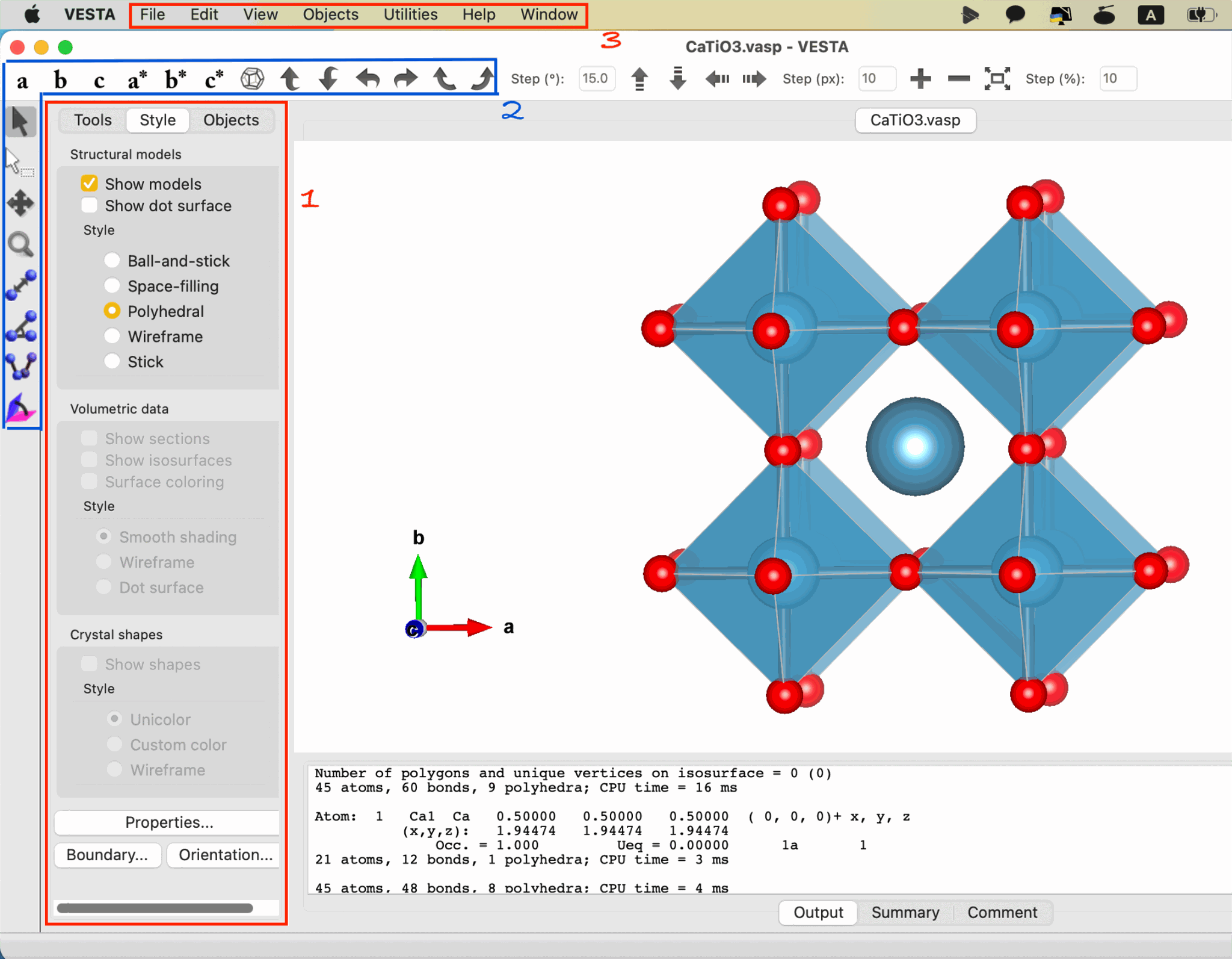
The same numbered labels are used here.
- Box 1: Style panel: Select Polyhedral.
- Box 2: View/orientation toolbar: Rotate the structure or align it along a specific lattice direction.
- Box 3: Menu bar: Open [Edit] -> [Bonds] when defining the coordination environment.
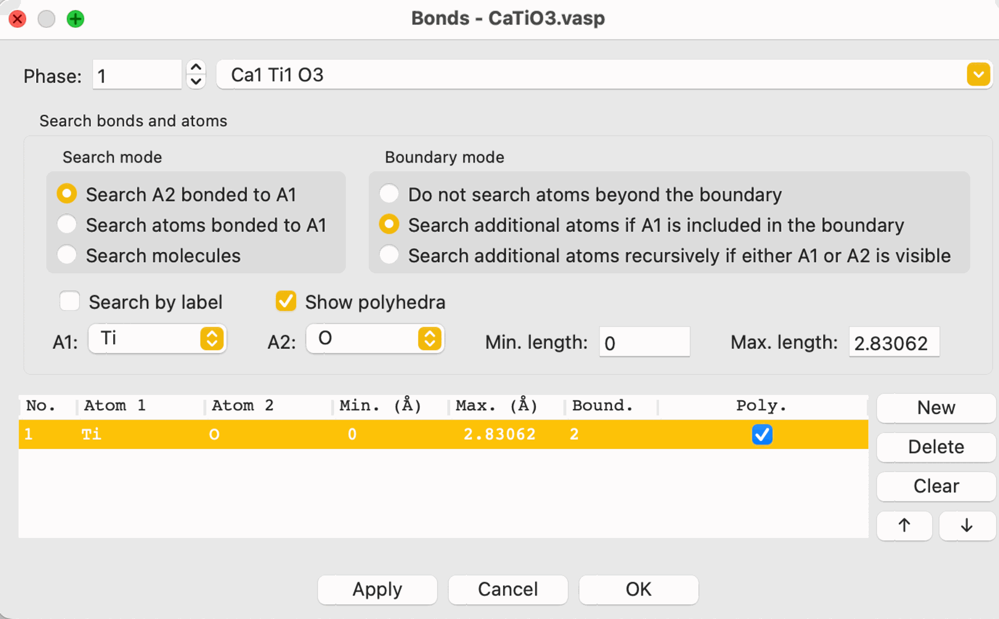
3.3 Define Ti-O Bonds
Open:
[Edit] -> [Bonds]
Define the Ti-O bond:
A1: Ti
A2: O
Set the maximum bond length so that the nearest O atoms around Ti are included, then enable:
Show polyhedra
4. Reading a VASP Structure File
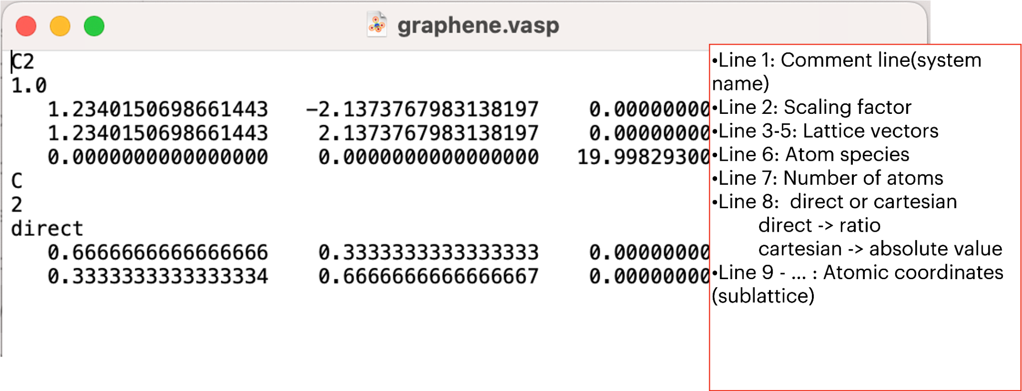
A typical POSCAR file is organized as follows:
Line 1       Comment
Line 2       Scaling factor
Lines 3-5    Lattice vectors
Line 6       Atomic species
Line 7       Number of atoms
Line 8       Direct or Cartesian
Line 9-...   Atomic coordinates
The number of coordinate lines, from Line 9 to the end of the file, must match the total number of atoms given above, i.e. the sum of the values in Line 7.
Direct Coordinates
In Direct format, atomic positions are expressed as fractional coordinates with respect to the lattice vectors in Lines 3-5.
Cartesian Coordinates
In Cartesian format, atomic positions are given directly in Cartesian coordinates.
4.1 Connecting POSCAR Text to Atoms in VESTA
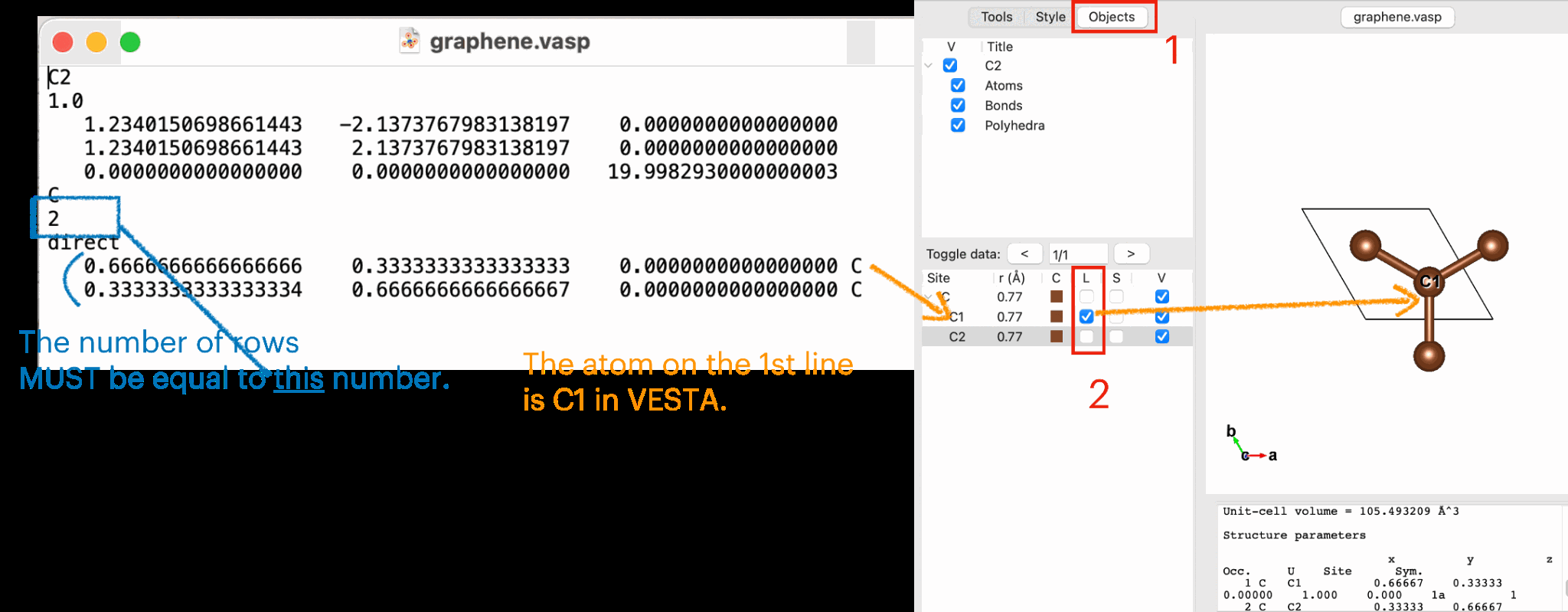
This will come in handy when you want to customize the structure.
- Blue: The number of coordinate rows in the POSCAR must match the atom count given above.
- Red 1: Objects button: This displays a list of the atomic coordinates from the text file, as shown above.
- Red 2: Atom list: The first coordinate line in the POSCAR corresponds to the first atom entry in VESTA, which is C1 in this example.